Turning a detection into a physical action
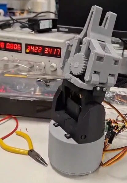
The project began with the ambition of automating e-waste sorting using a five-degree-of-freedom robotic arm. We narrowed the implemented prototype to batteries: find an object in a camera image, estimate its position and move it to a designated sorting area.
This created a practical engineering challenge. A detector could identify a battery, but a successful pickup also depended on camera calibration, coordinate mapping, motor capability and gripper behaviour.
My contribution
My contribution focused on computer vision: preparing the image datasets, training the detector and implementing object-detection code.
- Dataset preparation: I gathered and prepared image datasets and adjusted the data for the OpenCV and Python workflow.
- Annotation: I labelled battery bounding boxes and classes using LabelImg.
- Model training: I trained YOLOv4-tiny using the prepared dataset.
- Detection code: I implemented Python/OpenCV code to locate objects in camera images and label their classes.
I also contributed to broader project planning and the waste-management background. The full prototype was a team outcome, combining this vision work with stereo depth estimation, camera calibration, mechanical design and servo control.
The training images needed to match the camera
Our initial open-source e-waste dataset did not match the viewpoint and conditions of the robot's camera. That mismatch made dataset relevance a central challenge for the vision work.
We collected 151 battery photographs using a Logitech Pro 9000 webcam and annotated bounding boxes with LabelImg. Augmentation covering lighting, brightness, size, blur and orientation expanded the dataset to 318 images.
This gave the project images closer to the intended operating conditions. It also left a clear limit: augmented versions of a small source collection do not provide the same evidence as independently collected test images.
How the team connected vision and movement
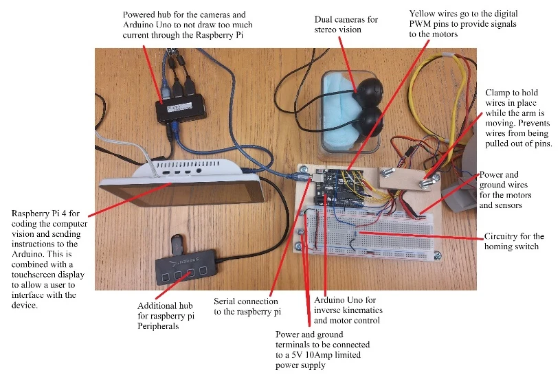
The project used YOLOv4-tiny, trained and fine-tuned in GPU-enabled Google Colab, with OpenCV on a Raspberry Pi 4 during integration.
- Detect the battery. The vision pipeline identified the target in the camera image.
- Estimate its depth. A stereo pair used calibration from 30 paired checkerboard captures. Rectified images and block matching supplied disparity-based depth estimates.
- Translate the position. Camera-to-robot coordinate mapping converted the estimated target location into the arm's working frame.
- Move and grasp. The Raspberry Pi communicated target positions to an Arduino Uno. Inverse kinematics and servo movements positioned the gripper for pickup and transfer.
From component tests to an assembled mechanism
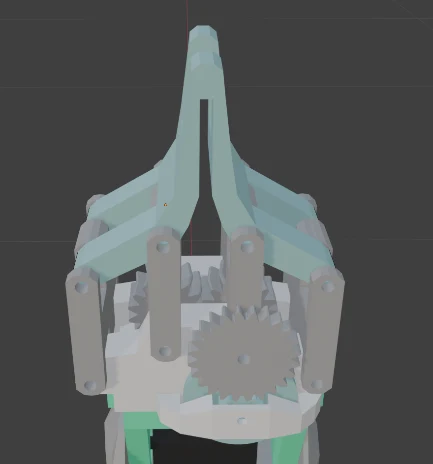
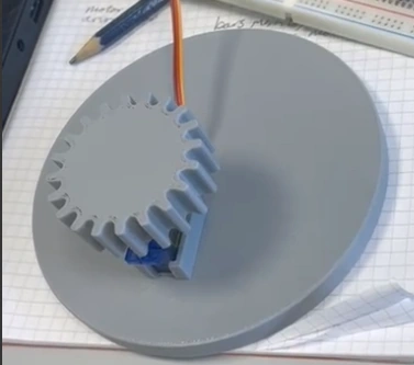
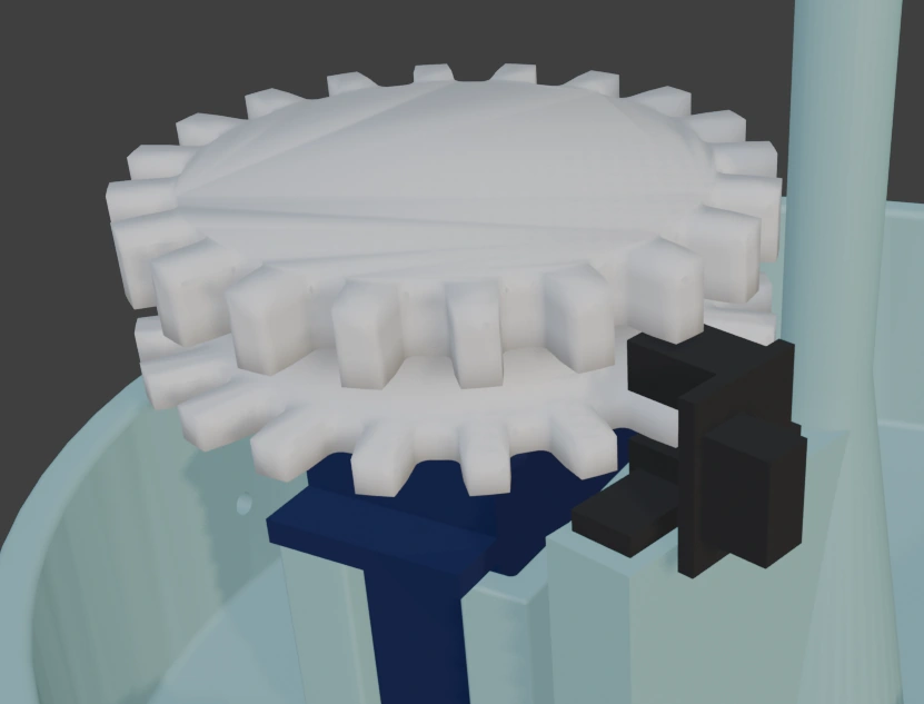
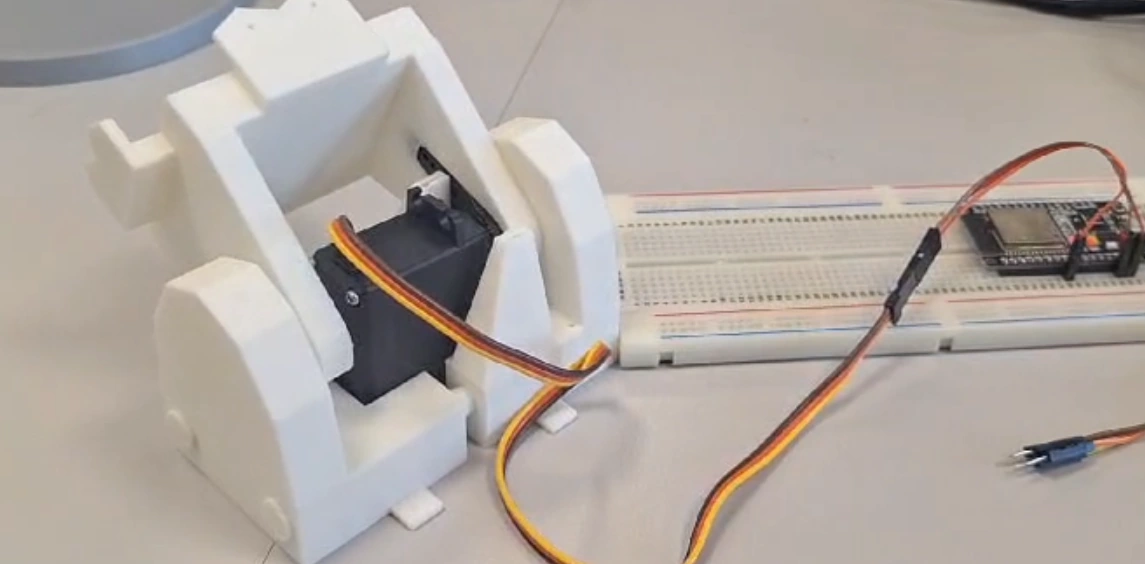
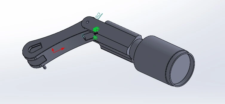
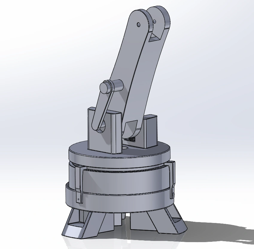
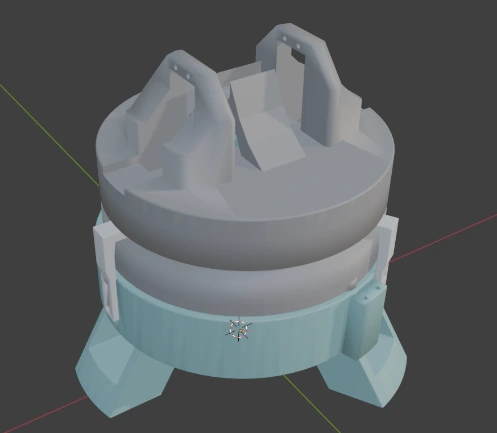
The team tested and revised the mechanism as the vision and control components came together. These original photographs and CAD views show the development behind the prototype. They document the team's mechanical work alongside my vision contribution.
Select any figure to inspect it at full size.
What we demonstrated
The team integrated detection, position estimation and arm control into a laboratory prototype that picked up batteries and transferred them to a designated area.
Calibration trials showed that the placement of reference points affected coordinate mapping. Spreading the points across the working area, including a raised point, improved the mapping used to position the arm.
The working prototype demonstrates laboratory feasibility. Reliable operation across different lighting, camera arrangements and battery appearances would need further testing. The project did not establish a measured production sorting rate or aggregate grasp-success rate.
What I took from the vision work
The project connected my work on images and detection to the constraints of a physical system. It showed me the importance of matching training data to the actual camera view and testing the complete path from detection to action.
It also developed my understanding of system-level failure: an accurate-looking detection can still lead to an unsuccessful pickup when depth estimates, coordinate mapping or mechanics are unreliable.
What I would improve next
- Test data: collect independent battery images across changes in lighting, orientation and background, with a clearly documented evaluation split.
- Separate measurements: record detection performance and physical pickup success separately, making failures easier to locate.
- Calibration and mechanics: make calibration easier to repeat and address torque constraints that prompted redesigns during the project.
- Grasp feedback: investigate a way to confirm that an object has been held. The prototype did not have pressure feedback.
The completed system focused on batteries. Broader e-waste categories, ROS integration and gripper feedback remained future development priorities.
Project evidence
University of Plymouth group project, E-Waste Sorting Robotic Arm. The prototype photographs and CAD figure come from the submitted group report.
My responsibilities are documented in Appendix C of the group report. The full document remains private; the figures shown here exclude the author contact details and contribution lists for other team members.